Flash fresh ESP8266 firmware on Eques Elf Smart Plug
I couldn’t find any information on this smartplug, so here is what I figured out through disassembly.
This smart plug seems identical to the CNCT Life intelliPLUG, and there is a great set of teardown photos at the FCC
PDF of breakdown photos
The daughtercard board included in the plug is an ESP8266EX, marked with this part number:
MNWIFIX09
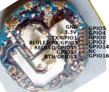
I took out the daughtercard and traced the pins. The are as follows:
                      ▼
               GND  * - | -  GPIO5
              3.3V  * - | -  GPIO4
         TXD/GPIO1  * - | -  GPIO0
   BLULED/RX/GPIO3  * - | -  GPIO2
REDLED/MTDO/GPIO15  * - | - * MTMS/GPIO14
       MTCK/GPIO13  * - | -  N/C
 BUTTON/mtdi/GPIO12 * - | -  XPD_DCDC/GPIO16/WAKEUP

* soldered to main board
I am pretty sure the relay and RED LED are tied to the same pin – if the LED is on, the relay is on.
See a ESP8266 pinout page for details, such as this example.
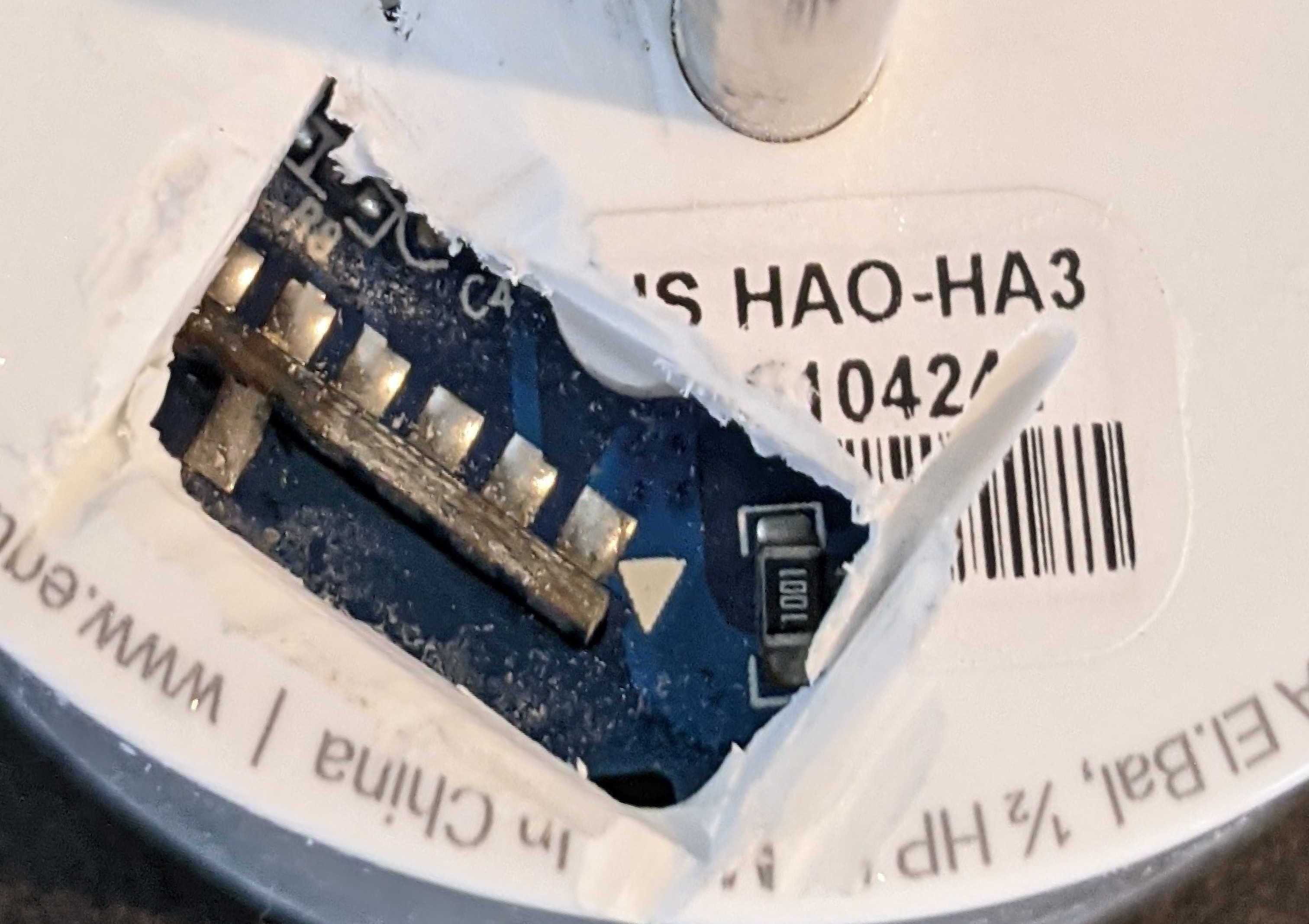
In order to access the pins, I created a small hole on the plug side with a Dremel.
In order to progam the ESP8266, the top 4 left pins (GND, 3.3V, TX, RX) and the third pin on the right (GPIO0) need to have jumper wires installed. I found it easiest to solder GPIO0 (green wire in picture), followed by GND -> RX.
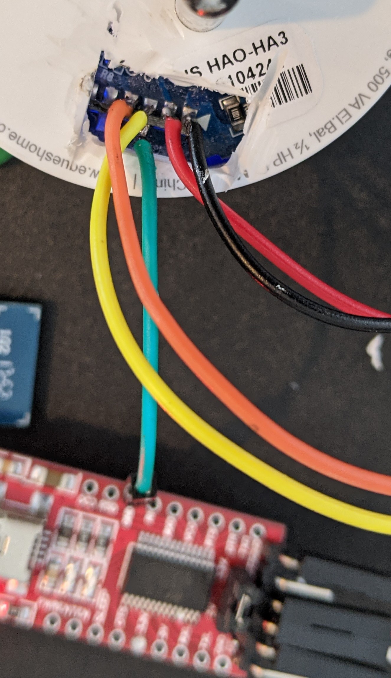
At this point it is ready to program. Connect with a FTDI232 board, ground GPIO0 before powering the board, and assuming all the pins are correctly hooked up to the FTDI232 board, esptool should be able to read it.